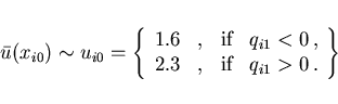
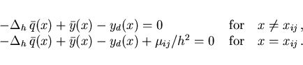
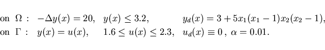
Example 5.1: To enable a comparison, we consider first the example in Bergounioux, Kunisch [3], Section 5.2, with the following data:
The following results were obtained, they are explained below:
Cost functional :
![]() , CPU seconds : 96
, CPU seconds : 96
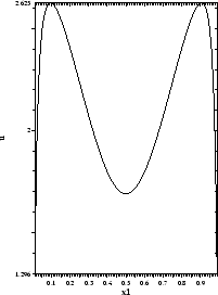
The optimal control is shown in Figure 1.
The optimal state and adjoint variable are not shown here,
because they are very
similar to those in Figure 3 where
![]() is replaced by
is replaced by
![]() .
It should be noted that the output of Lagrange multipliers is provided by AMPL.
It is no difficulty for primal-dual methods to produce multipliers since, in
fact they are variables that are computed simultaneously with the primal
problem variables.
The control constraints are not active while the state variable attains
its upper bound only
in the center
.
It should be noted that the output of Lagrange multipliers is provided by AMPL.
It is no difficulty for primal-dual methods to produce multipliers since, in
fact they are variables that are computed simultaneously with the primal
problem variables.
The control constraints are not active while the state variable attains
its upper bound only
in the center
![]() of the unit square with dual variable
of the unit square with dual variable
![]() .
This is in agreement with the results in [3].
It can be checked that the adjoint equation (3.6) holds in the
discretized version with
.
This is in agreement with the results in [3].
It can be checked that the adjoint equation (3.6) holds in the
discretized version with
![]() denoting the discretized Laplacian,
denoting the discretized Laplacian,
This example will also be used to illustrate the numerical process in more
detail.
In Table 1 we summarize the data: size of grid, number of
iterations of LOQO, times in seconds for the AMPL compilation
and the solution by LOQO,
the accuracy as the number of correct significant digits in the objective
function value. The primal-dual approach yields upper and lower bounds for
this value and thus permits such a statement. In all the following examples
this accuracy measure was at least 8 and is therefore not listed.
Finally, we list the objective
function value and one representative value of both the state and the control
variable. While the state variable not far from the active center point has
a small error, the control at the midpoints of the edges still varies in
the fourth digit. Thus, ![]() was chosen for the subsequent calculations.
Since the AMPL times were in the range of a few seconds or a few percent of
the solution times they will not be given below.
was chosen for the subsequent calculations.
Since the AMPL times were in the range of a few seconds or a few percent of
the solution times they will not be given below.
We compare LOQO and other solvers with AMPL interface available to
us in Table 2.
For ![]() not all the codes considered (LANCELOT-A, MINOS-5.5, SNOPT-5.3,
BPMPD-2.21; links to all codes in [21]) were successful.
Therefore, results are listed for
several coarser grids as well as for the finest grid used with LOQO.
Given are CPU times on the same platform used above, but scaled to LOQO's
time. MINOS reports one problem as infeasible while SNOPT reports two problems
as unbounded. The reason for these messages may also be a "bad starting guess".
All solvers were given the same AMPL file and AMPL initializes variables
with zero.
For
not all the codes considered (LANCELOT-A, MINOS-5.5, SNOPT-5.3,
BPMPD-2.21; links to all codes in [21]) were successful.
Therefore, results are listed for
several coarser grids as well as for the finest grid used with LOQO.
Given are CPU times on the same platform used above, but scaled to LOQO's
time. MINOS reports one problem as infeasible while SNOPT reports two problems
as unbounded. The reason for these messages may also be a "bad starting guess".
All solvers were given the same AMPL file and AMPL initializes variables
with zero.
For ![]() all solvers except LOQO and BPMPD exceeded the
available memory (256MB).
The convex QP code BPMPD solves with increasing efficiency
compared to LOQO but this is only possible, because, in fact, Example 5.1 is
a convex QP problem. BPMPD is not applicable to most of the other examples
solved below.
For another comparison see Example 5.7.
all solvers except LOQO and BPMPD exceeded the
available memory (256MB).
The convex QP code BPMPD solves with increasing efficiency
compared to LOQO but this is only possible, because, in fact, Example 5.1 is
a convex QP problem. BPMPD is not applicable to most of the other examples
solved below.
For another comparison see Example 5.7.
Example 5.2:
All data are the same as in Example 5.1 except that
we choose
![]() instead of
instead of
![]() .
According to the optimal control law (3.11) we can expect either a
bang-bang or a singular control. We find the following results:
.
According to the optimal control law (3.11) we can expect either a
bang-bang or a singular control. We find the following results:
Cost functional :
![]() , CPU seconds : 78
, CPU seconds : 78
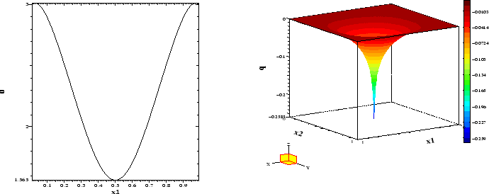
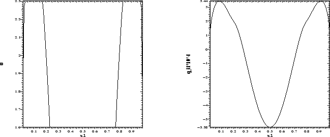
The optimal control, adjoint variable and optimal state are shown in
Figures 2 and 3.
Both the control and state constraints do not become active.
Hence, the optimal control is totally singular on ![]() .
This is in accordance with the control law (3.11) since
the normal derivative of the adjoint variable satisfies
.
This is in accordance with the control law (3.11) since
the normal derivative of the adjoint variable satisfies
![]() which follows from the numerical results
which follows from the numerical results
![]() in view of (4.4).
In Figure 3 as in Figures 5 and 7 below the vertical axis is labeled
in view of (4.4).
In Figure 3 as in Figures 5 and 7 below the vertical axis is labeled
![]() since for these examples both the state and the control are plotted in
these figures.
since for these examples both the state and the control are plotted in
these figures.
Example 5.3:
The data are the same as in Example 5.1 except that
we choose more restrictive state and control constraints:
We obtain the following results:
Cost functional :
![]() , CPU seconds : 103
, CPU seconds : 103
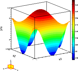
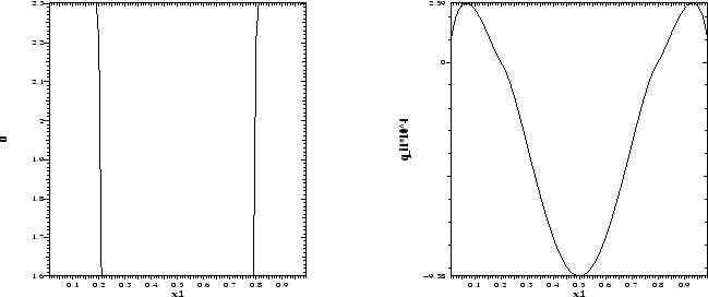
The optimal control, state and adjoint variable are shown in Figures 4 and 5.
The optimal control is continuous and has
two boundary arcs with
![]() and one boundary arc with
and one boundary arc with
![]() . The junction points with the boundary are the
points
. The junction points with the boundary are the
points
![]() on the bottom edge of
on the bottom edge of ![]() .
By inspecting the switching function in Figure 4,
we can verify the control law (3.10).
The assumption
.
By inspecting the switching function in Figure 4,
we can verify the control law (3.10).
The assumption
![]() underlying (3.10) obviously holds.
Let us check the control condition on the
bottom edge of
underlying (3.10) obviously holds.
Let us check the control condition on the
bottom edge of ![]() at the points
at the points ![]() .
Observe that
.
Observe that
![]() according to (4.22) since we have
according to (4.22) since we have ![]() .
Then in view of
.
Then in view of
![]() the control law (3.10) takes the form
the control law (3.10) takes the form

Example 5.4:
The data are those from Example 5.3 but now we choose
![]() expecting to obtain a bang-bang control in contrast to
the totally singular control in Example 5.2. This expectation is met
with the following results:
expecting to obtain a bang-bang control in contrast to
the totally singular control in Example 5.2. This expectation is met
with the following results:
Cost functional :
![]() , CPU seconds : 116
, CPU seconds : 116
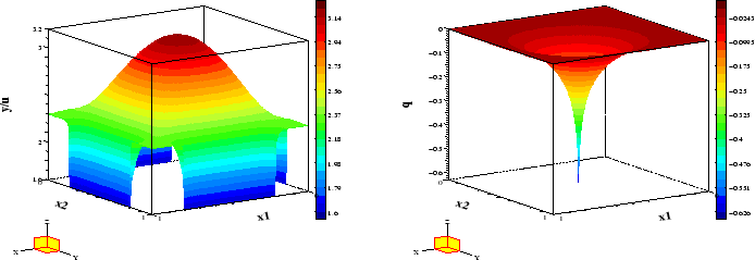
The optimal control shown in Figure 6 is indeed bang-bang.
The switching function on the bottom edge of ![]() is
is
![]() according to (4.22).
Then Figure 6 clearly illustrates the control law (3.11):
according to (4.22).
Then Figure 6 clearly illustrates the control law (3.11):